Power PC G5
POWER stands for Power Optimization With Enhanced RISC and is the main processor in many IBM servers, workstations, and supercomputers of single-chip performance today.
The PC in PowerPC stands for performance computing. Descended from the POWER architecture, it was introduced in 1993. It was designed from the beginning to run on a broad range of machines, from battery-operated handhelds to supercomputers and mainframes. But it saw its first commercial use on the desktop, in the Power Macintosh 6100.
Born of an alliance between Apple, IBM, and Motorola (also known as the AIM alliance), the PowerPC was based on POWER, but with a number of differences. For instance, PowerPC is open-endian, supporting both big-endian and little-endian memory models, where POWER had been big-endian. The original PowerPC design also focused on floating-point performance and multiprocessing capabilities. Still, it did and still does include most of the POWER instructions. Many applications work on both, perhaps with a recompile to make the transition.
PowerPC is based on the POWER Architecture designed by Motorola. A collaboration
by IBM, Apple, and Motorola has made this RISC chip very successful.
PowerPC G5 is a RISC highly parallel implementation of the PowerPC architecture,
( IBM) capable of handling large number of tasks at the same time. Power
PC instruction set was designed to handle both 32 bit and 64 bit code,
thus 32 bit applications can run natively on PowerPC G5 based computers.
Architecture
Virtual address range: 64 bits, or 18exabites
Physical address range: 42 bits or 4 terabytes
64 bit data path and registers
Native support of 32-bit application code
64K L1 instruction cache; 32K L1 data cache, parity protected
512 internal L2 cache
General purpose registers (GPRs)
- 32 GPRs (GPR0 -GPR31)
- Are source and destination of all integer operations.
- Are the source for address operands for all load/store operations.
- Provide access to Special purpose registers (SPRs)
- All GPRs are available for use with one exception: in certain instructions, GPR0 simple means the value 0, and no lookup is done for GPR0’s content.
Floating point registers (FPRs)
- 32 FPRs (FPR0 - FPR31)
- Are source and destination of all floating-point operations and can contain 32-bit and 64-bit signed and unsigned integer values, as well as single-precision and double precision floating point values.
- Provide access to the Floating-Point Status and Control register (FPSCR)
Special purpose registers (SPRs)
Give status and control of resources within the core.
SPRs that can be read and written include:
Count register, Link register, Integer exception register
- Instruction address register (IAR)
Program counter, not directly available to the user - Link Register (LR)
Contains address to return to at the end of a function call. - Fixed-Point Exception Register (XER)
Contains carry and overflow information from integer arithmetic operations - Count Register ( CTR)
Contains a loop counter that is decremented on certain branch operations. - Condition Register (CR)
Used to reflect the result of instruction operations such as Equal, Greater Than, Less Than, etc. - Processor Version operator (PVR)
32 bit only register that identifies the version and revision level of the processor.
Access to the PVR is privileged.
Three register files, each holding 32 architected values and 48 rename registers
- One general-purpose register file to contain 64-bit registers for integer calculations
- One floating-point register file to contain 64-bit registers for floating-point calculations
- One vector register file to contain 128-bit registers for vector calculations
Addressable Memory -[back to top]
The G5 processor fully supports Big-Endian mode and has limited support with Little-Endian mode based on implementation.
The move to 64-bit processing results in a similarly dramatic leap in the amount of memory supported. Computers keep track of data stored in memory using memory addresses. A memory address is a special kind of integer, which points to one byte in memory. Since memory addresses are computed in 64-bit registers capable of expressing 18 billion billion integers, the PowerPC G5 can theoretically address 18 exabytes (18 billion billion bytes) of virtual memory. In practice, memory addressing is defined by the physical address space of the processor. The PowerPC G5, with 42 bits of physical address space, supports a colossal 242 bytes, or 4 terabytes, of system memory. Although it’s not currently feasible to purchase 4 terabytes of RAM, the advanced architecture of this processor allows for plenty of growth in the future.
- All storage is byte addressable
- Supports byte (8-bit), halfword (16-bits), word (32-bit) and doubleword (64-bit) data types.
- 32-bit PowerPC implementation support a 4-gigabyte effective address space
- 64-bit PowerPC implementation support a 16-exabyte effective address space
- Primarily big-endian machines but support for little-endian varies by implementation
Integer Representation -[back to top]
Supports signed and unsigned numbers
Unsigned
- Byte
- Word
- Double
- Quad
Signed
- 2’s complement representation
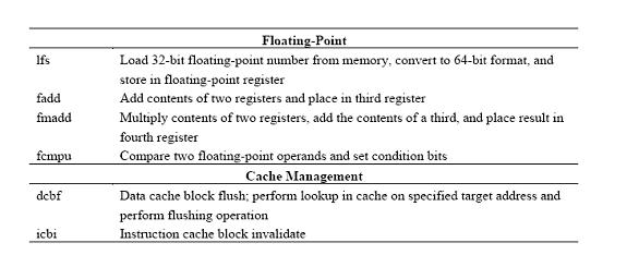
Floating Point Representation -[back to top]
Defines two different binary fixed-length format
- 64-bit double format for double-precision format
- 32-bit single format for single-precision format
IEEE Operations -[back to top]
Double Precision
- Bias 1023 (2^(11-1)-1)
- 1-bit sign, 11-bit exponent, and 52-bit fraction
Single Precision
- Bias 127 (2^(8-1)-1)
- 1-bit sing, 8-bit exponent, and 23-bit fraction
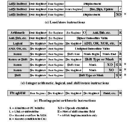
Instruction Format -[back to top]
All instructions in the PowerPC are 32-bit long and follow
a regular format.
The first 6 bits of an instruction specify the operation to be performed.
In some cases, there is an extension to the opcode elsewhere in the instruction
that specifies a particular subcase of an operation.
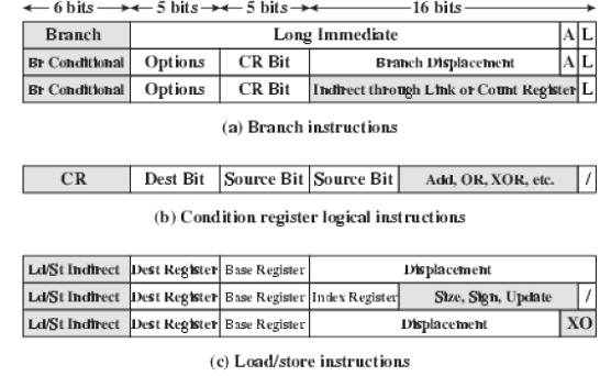
For all load/store, arithmetic, and logical instructions,
the opcode is followed by two 5-bit register references, enabling 32 general-purpose
registers to be used.
The branch instructions include a link (L) bit that indicates that the
effective address of the instruction following the branch instruction
is to be placed in the link register. Two forms of the instruction also
include a bit (A) that indicates whether the addressing mode is absolute
of PC relative. For the conditional branch instructions, the CR bit field
specifies the bit to be tested in the condition register.
Most instructions that result in a computation (arithmetic, floating-point
arithmetic, logical) include a bit that indicates whether the result of
the operation should be recorded in the condition register.
Floating-point instructions have filed for three source registers. In
many cases only two source registers are used. A few instructions involve
multiplication of two source registers and then addition or subtraction
of a third source register.
Addressing Modes -[back to top]
PowerPC uses a simple and relatively straightforward set of addressing
modes.
These modes are conveniently classified with respect to the type of instruction.
Load/Store Architecture
The PowerPC provides two alternative addressing modes for load/store instructions: indirect addressing and indirect indexed addressing.
Indirect Addressing: the instruction includes a 16-bit displacement to be added to a base register, which may be any of the general-purpose registers. In addition, the instruction may specify that the newly computed effective address is to be fed back to the base register, updating the current contents. The update option is useful for progressive indexing of arrays in loops.
Indirect Indexed Addressing: the instruction references a base register and an index register, both which may be any of the general-purpose registers. The effective address is the sum of the contents of these two registers.
Branch Addressing
Three branch addressing address modes are provides: Absolute addressing, Relative addressing and Indirect addressing.
Absolute Addressing: when is used with unconditional branch instructions,
the effective address of the next instruction is derived from a 24-bit
immediate value within the instruction. The 24-bit value is extended to
a 32-bit value by adding two zeros to its least significant end and sing
extending. For conditional branch instructions, the effective address
of the next instruction is derived from a 16-bit
immediate value within the instruction. The 16-bit value is extended to
32-bit value by adding two zeros to its least significant end and sing
extending.
Relative Addressing: the 24-bit immediate value (unconditional branch) or 14-bit immediate value (conditional branch) is extended as before. The resulting value is then added to the program counter to define a location relative to the current instruction.
Indirect Addressing: is the other conditional branch addressing, this
mode obtains the effective address of the next instruction from either
the link register or the counter register.
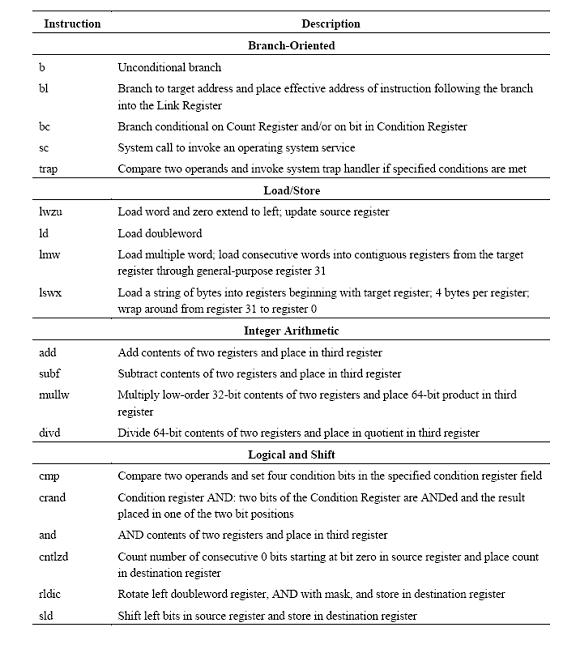
Instruction Set -[back to top]
The PowerPC provides a large collection of operations types.
Arithmetic Instructions
For integer arithmetic, all operand must be contained either in registers
or as part of the instruction. With register addressing, a source or destination
operand is specified as one of the general-purpose registers. With immediate
addressing, a source operand appears as a 16-bit signed quantity in the
instruction.
For floating-point arithmetic, all operands are in floating-point registers;
that is, only register addressing is used.
Branch-Oriented Instructions
Conditional branch instructions test a single bit of the condition register
for true, false or do not care and the contents of the count register
for zero, nonzero, or do not care. If the count register is tested for
zero or non zero, then it is decremented by 1 prior to the test.
Load/Store Instructions
Only load and store instructions access the memory locations; arithmetic
and logical instructions are performed only in registers. This is characteristic
of RISC design.
There are two features that characterize the different load/store instructions:
Data Size: data can be transferred in units of byte, halfword, word,
or doubleword.
Sign Extension: for halfword and word loads, the unused bits to the left
in the 64-bit destination register are either filled with zeros or ones.
Data Types Supported -[back to top]
The PowerPC can deal with data types of 8 (byte), 16 (halfword), 32 (word), and (doubleword) bits length. Some instructions required that memory operands be aligned on a 32-bit boundary. In general, however alignment is not required. One interesting feature of the PowerPC is that can use either little-endian or big-endian style. The processor interprets the contents of a given item or data depending on the instruction. The fixed-point processor recognizes the following data types:
Unsigned byte: used for logical or integer arithmetic operations. It
is loaded from memory into a general register by zero extending on the
left to the full register size.
Unsigned halfword: as for unsigned byte, but for 16-bit quantities.
Signed halfword: used for arithmetic operations; loaded into memory by
sign extending on the left to full register size.
Unsigned Word: used for logical operation and as an address pointer.
Signed word: used for arithmetic operations.
Unsigned doubleword: used as an address pointer.
Byte string: from 0 to 128 bytes in length.
In addition, the PowerPC supports the single and double precision floating point data types defined in IEEE 754.
Source: Computer Organization & Architecture by William Stallings
Pipelining -[back to top]
Fetch - The PowerPC G5 anticipates the need for data and instructions and pre-fetches them into its large L1 and L2 caches.
To protect the integrity of data and instructions, L1 cache is parity-protected and L2 cache is protected using Error Correction Code (ECC) logic.
Fetch & Decode - A low-latency 512K L2 cache provides fast access to data and instructions—at rates up to 64 GBps. Instructions are fetched from the L2 cache into a direct-mapped 64K L1 instruction cache. At the same time, 32K of write-through, two-way associative L1 data cache can fetch up to eight active data streams simultaneously.
Up to eight instructions per clock cycle are fetched from the L1 instruction cache for decoding.
Highly accurate dynamic prediction - Up to 2 branches per cycle, 98% accuracy
Note: Decoding divides each instruction into smaller sub-operations, giving the processor more freedom to schedule execution of code in parallel.
Multiple pipelined execution units, branch prediction, and a SIMD, or
vector processing (Altivec) unit.
Up to 215 in-flight instructions
With each clock cycle, up to eight instructions can be fetched from the direct-mapped 64K L1 instruction cache
32K of write-through, two-way associative L1 data cache can fetch up to eight active data streams, which are loaded into data registers behind the execution units
Different types of instructions are processed concurrently by the execution units, which include two floating-point units, two integer units, two load/store units, a condition register unit, a branch prediction unit, and a vector processing unit
Refer to Figure 1 for details.
Microprogramming -[back
to top]
Uses a “RISC-like” hardwired implementation.
This allows faster execution
Simpler micro-codes
Inside the processor - Milli-coded instructions are decoded into simpler instructions . During each clock cycle the PowerPC microprocessor can send a group of five simpler instructions into its execution units.
These instructions are broken down into similar groups for instruction execution, memory slots 0-3 are reserved for micro-instructions.
Most micro-operations occupy slots 0 to 3 in the processor.
When the entire group of micro-instructions is executed, and all preceding groups are also executed, the processor writes down the final results and the Group Completion Table gets cleared.
A Group Completion Table indicates the maximum size of a continuous instruction block (as if cut out of the program) that can be processed by the processor at a given moment
To be exact, this is the maximum number of processed micro-instructions, which the instructions from the continuous part of the program are translated into.
Note: The Group Completion Table size will be increased if the processor has a long pipeline.
Interconnections -[back to top]
Frontside Bus Up To 1.25GHz:
Designed to harness the power of the PowerPC G5 processor, a
1.25GHz, 64-bit bidirectional Double Data Rate (DDR) frontside bus maximizes
throughput between the processor and the system controller. And unlike
most processor interfaces, which can carry data in only one direction
at a time and waste precious time changing directions, the PowerPC G5
features two high-speed unidirectional 32-bit data paths — one flowing
continuously into the processor and one flowing from the processor. This
lets data move in opposite directions simultaneously, with no other demands
on the data stream and no wait time while the processor and system controller
compete for use of the bus. What’s more, the data streams integrate
clock signals along with the data, allowing the frontside bus to work
at speeds of up to 1.25GHz for an astonishing 10GB per second of aggregate
bandwidth.
Independent Buses:
Each G5 processor has its own dedicated bidirectional interface to the
system controller. That’s a mind-boggling 20GB per second of total
bandwidth on dual 2.5GHz systems — more than twice the 6.4GBps maximum
bandwidth of Pentium 4-based systems using the latest PC architecture.
In addition to providing fast access to main memory, this high-performance
frontside bus architecture enables each PowerPC G5 processor to discover
and access data in the other processor’s L1 and L2 caches for ultrafast
performance.
Sources for Pipelining, Interconnections, and Microprogramming:
Apple Computers. June 2004. POWERPC G5 White Paper“.
Apple G5 Computers”.http://www.apple.com/g5processor/.
“IBM PowerPC G5: Another World”.http://www.xbitlabs.com/articles/cpu/display/powerpc-g5_11.html.
01/27/2004, 11:36 AM.
Memory -[back to top]
The PowerPC G5 128-bit memory controller supports fast 400MHz, DDR SDRAM
-synchronous dynamic random access memory.
It enables main memory to address two banks of SDRAM at a time, reading
and writing on both the rising and falling edge of each clock cycle. This
effectively doubles the bandwidth, enabling the Power Mac G5 to reach
a maximum memory throughput of up to 6.4GB per second. In addition, direct
memory access (DMA) works with the point-to-point system controller to
give each subsystem, such as PCI cards and graphics processing units ,
its own 6.4GBps interface to main memory, without having to utilize your
processor.
Eight DIMM slots, and can hold up to 8GB of DDR memory, which is ahead
of it’s time.
Buyers Note: Typically a PowerPC G5 has 512 MB standard.
32-bit PCs can hold only 4 GB max
Any more memory utilization would be accessed via virtual memory which
is 40 x slower than RAM.
Therefore, the PowerPC memory utilization can be up to 40x faster compared
to a PC.
However, this is not really vital now because most systems do not have
nor need that much memory.
Cache -[back to top]
Has two L1 and one L2 memory caches.
L1 Instruction Cache ( I-Cache ) 64K Direct Mapped Larger than Data Cache
L1 Data Cache ( D-cache ) 32K 2-way Associative 128 bytes per line Write-Thru
L2 Cache 512K 8-way Associative
G5 has no L3 Cache
800-1000MHz bus speeds
Transfer rates of 6.4GB per second
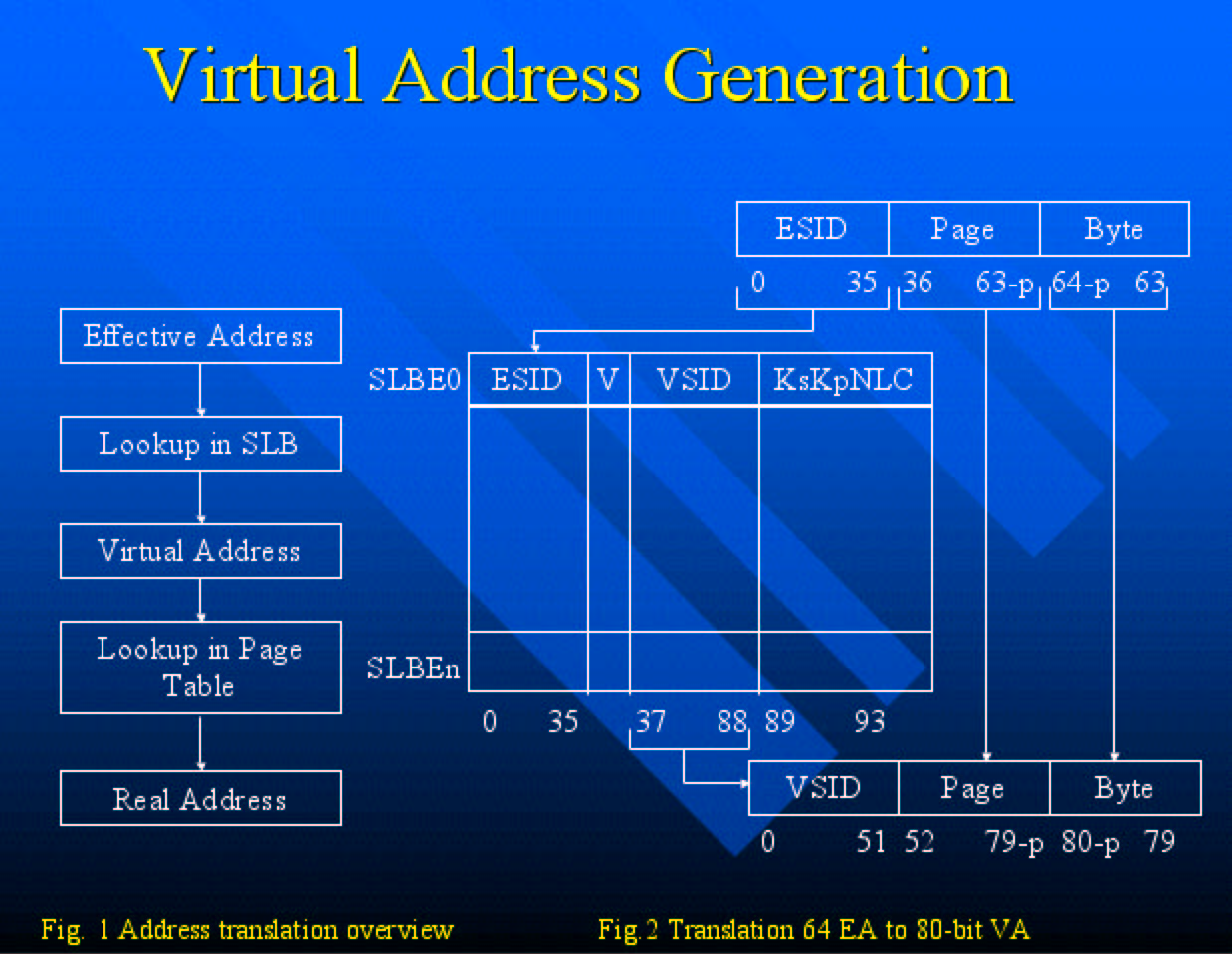
Virtual Memory -[back to top]
Each program can access 264 bytes of “effective Address (EA) space.
Each program space is a subset of a larger “Virtual address”
(VA) space managed by the operating system.
The operating system manages the real (physical) storage resources of
the system, by setting up the tables used by the hardware address translation
mechanism.
Sources for Memory, Cache, and Virtual Memory:
PowerPC G5 White Paper. January 2004, Apple Computer Inc.
Apple – Power Mac G5 - Architecture. http://www.apple.com/powermac/architecture.html.
PowerPC Operating Environment Architecture. Book 3 ver 2.01.
IBM.
|