Full Instruction Set
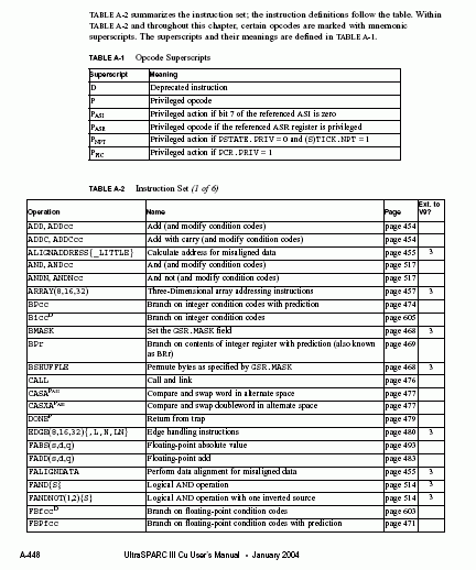
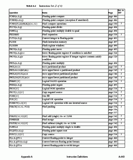
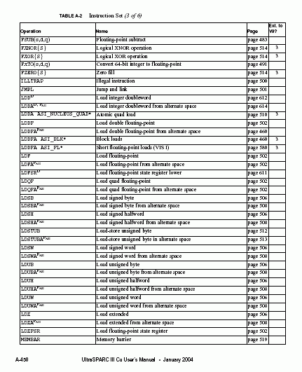
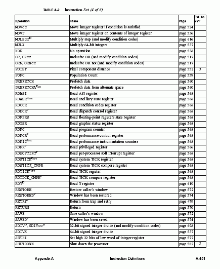
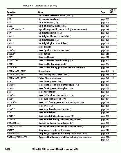
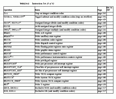
The integer arithmetic instructions are generally triadic register address instructions that compute aresult of afunction of two source operands. They either write the result into the destination register r[rd] or discard it. One of the source operands is always r[rs1]. The other source operand depends on the i bit in the instruction. If i = 0, then the operand is r[rs2]. If i = 1, then the operand is the immediate constant simm10, simm11, or simm13 sign-extended to 64 bits.
The arithmetic/logical/shift instructions perform arithmetic, tagged arithmetic, logical, and shift operations. One exception is the SETHI instruction that can be used in combination withanother arithmetic or logical instruction to create a 32-bit constant in an r register.
Condition CodesMost integer arithmetic instructions have two versions: one sets the integer condition codes (icc and xcc) as a side-effect; the other does not affect the condition codes.
Integer Add and Subtract InstructionsSixty-four bit arithmetic is performed on two r registers to generate a 64-bit result. The icc and xcc condition codes can optionally be set.
Tagged Integer Add and Subtract InstructionsThe tagged arithmetic instructions assume that the least significant two bits of each operand are a data-type tag. These instructions set the integer condition code (icc) and extended integer condition code (xcc) overflow bits on 32-bit (icc) or 64-bit (xcc) arithmetic overflow.
Integer Multiply and Divide InstructionsThe integer multiply instruction performs a64 × 64 . 64-bit operation; the integer divideinstructions perform 64 ÷ 64 . 64-bit operations. For compatibility with SPARC V8, 32 × 32 . 64-bit multiply instructions, 64 ÷ 32 . 32-bit divide instructions, and the multiply step instruction are provided. Division by zero causes a division_by_zero exception. Some versions of the 32-bit multiply and divide instructions set the condition codes.
Set High 22 Bits of Low WordThe “set high 22 bits of low word of an r register” instruction (SETHI) writes a22-bit constant from the instruction into bits 31 through 10 of the destination register. It clears the low-order 10 bits and high-order 32 bits, and it does not affect the condition codes. It is primarily used to construct constants in registers.
IU Logic InstructionsADD, ANDN, OR, ORN, XOR, XNOR Instructions These are standard logic operations that work on all 64 bits of the register. The instructions can optionally set the integer condition codes (icc/xcc).
FP Arithmetic InstructionsSingle-precision and double-precision FP is executed in hardware. Quad precision (128-bit) instructions are recognized by the CPU and trapped so they can be emulated in software.
Absolute Value and Negate Instructions
These instructions use standard IEEE operation with some exceptions.
Square Root and Divide Instructions
The square root and divide instructions begin their execution in the FGM pipeline and block
new instructions from entering until the result is nearly ready to leave the pipeline and be
written to the register file.
FP Conversion Instructions
The following FP conversions are supported. Conversions do not generate fcc condition
codes.
Floating-Point to Integer
All floating-point precision to word and double/extended word integer conversions are supported.
Integer to Floating-PointWord and double/extended word integer to all floating-point precision number conversions are supported.
Floating-Point to Floating-PointAll floating-point precision to all floating-point precision number conversions are supported.
Compare InstructionsThe same precision operands are compared and the fcc condition codes are set.
Load and Store FSR RegisterThe FSR register is accessed by load and store instructions into and out of the floating-point register file.
Data Alignment InstructionThe data alignment instruction FALIGNDATA concatenates two registers (16 bytes) and stores acontiguous block of eight of these bytes starting at the offset stored in the GSR.ALIGN field.


